Issue No. 252〔Delivered Products & Systems〕
Large-capacity, Ultrahigh-efficiency, High-pressure Pumps for Seawater RO Desalination
Delivered to Carlsbad Desalination Plant in the U.S.
Author
Yasushi KAWAI*
Shuichiro HONDA*
Yumiko SEKINO*
- *
Fluid Machinery & Systems Company
1. Introduction
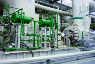
We delivered four units of the large-capacity, ultrahighefficiency, high-pressure pump to the Carlsbad Desalination Plant, seawater RO* desalination facilities located in California State, U.S.A. In the market of SWRO desalination, the pump boasts the world’s highest level of efficiency. Among the high-pressure pumps for the same purpose we have so far delivered, it provides by far the highest efficiency. Figure 1 shows one of the pumps delivered and installed in the plant. This chapter outlines the desalination technology and the plant using the pump and explains why high-efficiency pumps are required. Chapter 2 and the following explain the specifications and features of the pump, as well as a design technique for achieving ultrahigh-efficiency.
*RO stands for reverse osmosis.

Fig. 1 High-pressure pump for SWRO desalination
1.1 Underlying methods for desalination technology and market trends
Recent desalination technology uses one of the two mainstream methods: distillation or RO membrane. While the distillation method produces distilled water by heating seawater or other types of water, the RO membrane method produces fresh water by filtering pressurized seawater through a special membran called an RO membrane. In the world desalination market, the distillation method was dominant up to around 1995, following which the RO membrane method began to be dominant2).
1.2 Outline of the Carlsbad project and desalination plant1)

Fig. 2 Location of Carlsbad Desalination Plant and the overall project view1)
1.3 SWRO desalination process and the role of high-pressure pumps
This section explains the process by which seawater is turned into drinking water, using a layout drawing of the plant (Figure 3).
As Fig. 3 shows, seawater is taken in at Location ① and undergoes two-phase (first and second) pretreatment at Locations ② and ③ . The pretreated seawater is pressurized and filtered through an RO membrane to be turned into fresh water at Location ④ . Then, the fresh water undergoes post treatment at Location ⑤ to produce drinking water, before being distributed through Location ⑧ . The high-pressure pumps are installed at Process Location ④ to pressurize pretreated seawater.
While the distillation method uses thermal energy, the RO membrane method uses pressure energy converted from electric energy by the pumps. Generally in SWRO desalination facilities, the high-pressure pumps and their associated equipment are said to consume approximately 60% of the power required by all the processes. The costs for desalinating seawater, including electric charges, are borne as a water charge by the public supplied with drinking water. For this reason, to lower water cost, energy recovery equipment has been introduced to reduce the desalination costs, and the pump, the largest power consumer, in turn is required to perform at its highest efficiency.

Fig. 3 Carlsbad Desalination Plant and the process flow1)
2. Specifications and features of the pump
2.1 Specifications of the pump
| Application | High-pressure pump for SWRO desalination |
| Pump type | Axially split, multi-stage pump |
| Model name | Model SP/SPD |
| Features | • Axially-split-casing with betweenbearings and centerline support • Sleeve bearings |
| Flow rate | 12 848 USGPM(2918 m3/h) |
| Total head | 1845 ft(562.4 m) |
| Motor rated power | 7700 HP(5744.2 kW) |
Number of pumps delivered | 4 units (3 units for regular use and 1 unit for backup) |
2.2 Structural features of the pump
3. Design technique for achieving ultrahigh efficiency
3.1 Design of flow passage and manufacturing control
For several years, we have prototyped some full-size high-pressure pumps for SWRO desalination to verify the performance and functions. Based on the knowledge obtained through the prototyping in addition to our experience delivering many pumps of the same type, we designed from scratch the flow passage inside the pump, utilizing our own hydraulic design technology and computational fluid dynamics (CFD).
The pump has two stages. A double-suction impeller is adopted for the first stage impeller in view of the requirement for suction pressure. In designing the impeller, we used a three-dimensional inverse design method to optimize the meridional shape and blade loading distribution so that the pump efficiency at the design flow rate would be maximized.
Achieving high uniformity of the inlet flow of the impeller can prevent degradation of subsequent performance. Therefore we incorporated some ideas into the geometries of the suction chamber and the crossover passage, which connects the first-stage impeller with the second-stage impeller. The suction chamber was optimized by combining geometrical changes by using CFD and morphing technology, which was a new technology at that time. The geometry of the crossover passage was repeatedly modified using CFD. Eventually, losses in the crossover passage were reduced, and the velocity uniformity at the outlet of the crossover passage increased as well.
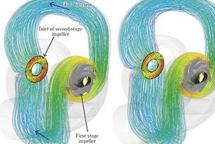
The optimized elements were combined and the performance of the entire pump was evaluated using CFD. Figure 4 shows the streamlines in the crossover passage and the time-averaged flow velocity distribution at the inlet of the second-stage impeller with unsteady CFD. The left and the right of Fig. 4 indicate those of the original geometry and the optimized geometry respectively. The distortion of the flow velocity of the optimized shape is smaller than that of the original shape.
To compare the performance predicted using the design technique above and that of the actual pump, the flow passage of the actual pump had to be manufactured with high dimensional accuracy. We measured the dimensions of the impellers and casing, which determine the performance, and verified their geometries using 3-D measurement and a geometry gauge (Figure 5). Based on the results, sections with a large amount of dimensional deviation were geometrically corrected so that the flow passage would match the designed geometry. The results of the performance test of the actual pump agreed well with the pump performance predicted by unsteady CFD. The design and manufacturing techniques can therefore be said to be effective.
The pump efficiency is affected by factors such as leakage losses in running clearance such as wear rings, disc friction loss on the back surface of impellers, and mechanical losses caused by bearings as well as hydrodynamic losses. In order to decrease leakage losses in wear parts, we reduced the wear ring gap in this pump design from that of conventional pumps of the same type, based on analysis of deflection and lateral vibration of the pump shaft.

Fig. 4 Streamlines in crossover passage and velocity distributions at inlet of the second-stage impeller (Left: original, Right: optimized)

Fig. 5 Verification of volute tongue geometry using geometry gauge
3.2 Casing structure design

Fig. 6 Results of FEM analyses on the casing structure
4. Conclusion
Water shortages have long been a global problem and are expected to become increasingly serious due to growing populations, climate change, and other factors. Under these circumstances, seawater desalination technology is one effective measure against water shortages as it can ensure a stable supply of fresh water from the sea–a giant water reservoir–independent of weather conditions. Among the underlying methods for this technology, the RO membrane method is expected to remain mainstream in desalination because of its cost advantage and lower CO2 emissions. We hope to continue to supply high-performance pumps in this field to help solve increasingly serious water shortages all over the world.
References
Recommended articles

Inquiry about Ebara Engineering Review